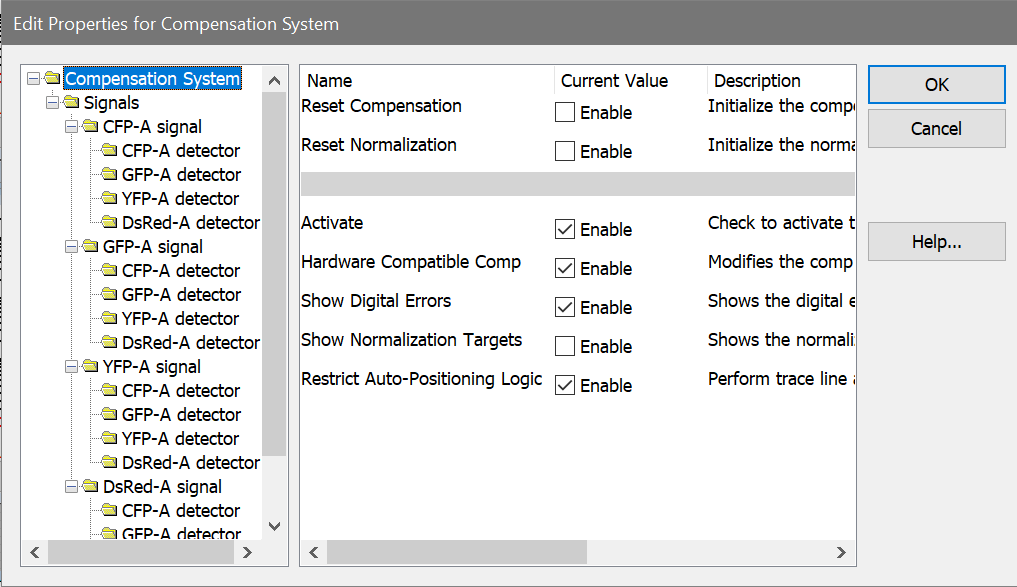
This dialog is displayed when the Edit button in the Compensation Toolbox dialog is clicked. It allows you to edit many of the characteristics of the compensation and normalization system.
The left-hand pane of the dialog displays a tree of compensation objects. The right-hand pane displays properties for the compensation object selected in the tree. When the dialog is initially displayed, general properties of the compensation system are shown.
Compensation System
This object shows general properties of the compensation and normalization system.
Reset Compensation
Check this option to reset the compensation trace lines so that the data is uncompensated. The compensation matrix is initialized for all parameters in the active data file.
Reset Normalization
Check this option to reset any normalization and restore the data to a non-normalized state. This affects normalization for all parameters in the active data file.
Activate
Enables or disables the N-Color Compensation™ and normalization systems. When unchecked, compensation and normalization are turned off. When checked, compensation and normalization are turned on.
Note: Trace lines disappear when compensation is activated. They are replaced by small + and - buttons.
Hardware Compatible Comp
When this option is enabled, the compensation matrix is constructed so that crossover is strictly subtractive. For example, these equations show hypothetical 3-color compensation with the Hardware option enabled:
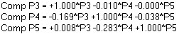
Notice that P3 is multiplied by 1.0 in the compensation of P3. This is also true for P4 in the P4 compensation, and P5 in the P5 compensation.
When the Hardware option is disabled, the compensation signal can be greater than 1.0 in the associated compensation expression:
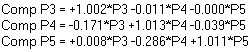
Notice that change in the expressions. In this setting, the loss of a signal due to signal crossover is adjusted for in the compensation matrix. This will result in slightly higher intensities than seen with the Hardware option enabled.
Show Digital Errors
When this option is enabled, the program draws dotted lines showing effects of digital error. The lines appear on 2P histograms that display parameters that are enabled for compensation in the Params to Compensate list. Use the Advice button to see information about the sources of digital error in the data.
Show Normalization Targets
Enable this option to display graphical elements that allow you to set normalization. Targets appear when the Activate option is enabled. See Normalization Targets for more information.
Restrict Auto-Positioning Logic
When enabled, WinList uses a more restricted portion of histograms to determine how to automatically position compensation Trace Lines. For most cases, this option will have little effect on how the program positions the trace lines. In some cases where there is significant signal crossover, enabling this option can improve the auto-positioning.
Signal Objects
Each parameter enabled for compensation has an associated Signal object in the tree control. When you select a Signal object, the following properties appear in the properties pane.
Normalization Factor
This field shows the current normalization factor applied to the selected signal parameter. The default value is 1.0, which means that the parameter has no normalization applied. You can enter a specific factor to apply, or use the Normalization Targets to adjust normalization graphically.
Detector Objects
Each Signal object contains Detector objects, one for each of the other parameters that is enabled for compensation. When you select a Detector object, the following properties appear.
Cross-over coefficient
This value represents the fraction of the Signal object parameter that is spilling over into this detector in the compensation system. A value of 1.00 (100%) is displayed for the detector associated with the signal parameter. A fractional value between 0.00 and 1.0 is displayed for the other detector objects. For example, a CD56-PE detector for a CD56-PE signal will display a value of 1.00. If 20% of a CD19-FITC signal is spilling into a PE detector, a value of 0.20 will be displayed for the PE detector of the CD19-FITC signal.
Compensation coefficient
This read-only field shows the fraction of the signal to add or subtract from the detector. It is computed in the construction of the compensation matrix and is not editable.
Digital Error Position
This read-only field displays the value between 0.0 and 1.0 that quantifies the digital error WinList computed for the parameter. Values of 0.85 and higher are relatively good, with little digital error. Values of 0.75 to 0.85 are fair. Values below 0.75 indicate that the parameter measurement contains a significant amount of digital error.
Use the Advice dialog to understand the sources of digital error.