Research
and Compliance Mode note:
In RUO mode, all users can perform these tasks.
In Compliance mode, only ModFitAdmins
and ModFitEditors have permission
to perform them.

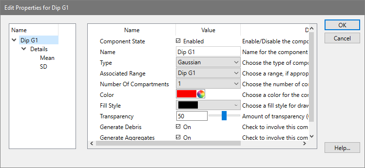
This dialog allows you to edit properties for a single model component. In addition, you can select and edit the properties for each detail of the component. Component details vary depending on the type of component.
A tree showing the component and its details is displayed on the left side of the dialog. Initially, the component itself is selected, and the list on the right shows the properties of that component.
When you click one of the details in the tree on the left, the properties for that detail will appear. See Edit Properties for Detail for more on this topic.
Component State:
This checkbox shows the current state of the component.
Name:
This edit box displays the name of the component. It can be edited by clicking inside the edit box and typing new text.
Type:
This drop-down list displays and selects the type of mathematical expression used for this component. Changing the type may also change the details, shown in the tree on the left of the dialog. See Model Descriptions for details on each model component type.
Associated range:
This drop-down list displays and selects the model range, if any, used to provide estimates to this model component. In most cases, ranges identify peak locations. They appear on the histogram when you click the Range button on the toolbar, or select Position ranges from the Analysis menu. If a component is not associated with a range, the selection will display "No range".
Number of compartments:
This list selects the number of sub compartments for the component. Some components, like the Polynomial, do not support more than one compartment. Setting this to 0 will disable the component.
Color:
Click this button to display the standard color selection dialog and choose a new color for the component.
Fill Style:
This list contains graphical fill options to use when drawing the component. Using a fill pattern allows an additional degree of transparency to overlapping components, in some cases, making it easier to review the model.
Transparency:
This option determines whether the component coloring will be transparent or not.
Generate Debris:
Enable this option if the population associated with the component contributes to debris in the sample. The debris modeling uses this to determine the expected shape of debris.
Generate Aggregates:
Enable this option if the population associated with the component contributes to aggregates in the sample. The aggregate modeling uses this to determine the expected shape of aggregates.
OK:
Click this button to accept the changes and close the dialog.
Cancel:
Click this button to cancel changes and close the dialog. This button may be disabled if changes are made that cannot be cancelled.
Help
Click this button to display online help for this topic.